종합 해킹툴이라고 거창해 보이지만 사실 기능은 몇가지 없다.
기능
0. 미세먼지 측정
1. 온습도 측정
-> lcd에 항상 값 표시
2. IR 센서로 신호 받고 IR LED로 받은 신호 그대로 보내기 (ex>적외선 리모컨 복사)
-> IR 센서는 항상 작동하도록하고 대신 스위치로 전류 차단 가능하게
-> IR LED는 버튼1 으로 제어 (버튼을 눌러 SEND MODE로 바꾸면, n초마다 작동)
3. RFID 카드 복제 (MIFARE만 가능)
-> 스위치로 전류 차단 (MISO, 3.3v)
-> 메모리 부족 문제로, uid 복제기능만을 메인 코드에 넣고 데이터 복제 기능은 따로 코드 작성해서 사용할때만 업로드.
-> 버튼2 으로 모드 변경. (카드 읽기 모드, 쓰기 모드)
-> 버튼1과 버튼2를 동시에 누르면 카드 읽기/쓰기 작동 (카드를 올려놓고 눌러야함. 누르지 않으면 카드를 올려놓아도 무반응)
부가적으로
0. 버튼제어
-> 버튼 2개 사용
-> 아날로그 입력 핀 하나만을 사용. 저항을 이용해 누르는 버튼에 따라 전압값이 변함.
1. led로 상태표시
-> 네오픽셀 led 2개 사용
-> 1개는 미세먼지 농도값에 따라 변화
-> 다른 하나는 모드에 따라 변화
2. 조도센서로 led 밝기 제어
-> 만들고 나서 느낀점은 밝기 변화가 맘에 안듬.
3. oled 디스플레이 사용
-> 센서값, 모드 상태 표시
부품 구매
0. 아두이노 나노 호환보드
http://mechasolution.com/shop/goods/goods_view.php?goodsno=575878&category=
1. PMS7003 미세먼지 센서 + 어댑터
2. DHT22 온습도 센서
http://mechasolution.com/shop/goods/goods_view.php?goodsno=540038&category=129003
3. 적외선 수신부 / IR Receiver
http://mechasolution.com/shop/goods/goods_view.php?goodsno=211&category=
4. 적외선 LED 850nm 발신
http://mechasolution.com/shop/goods/goods_view.php?goodsno=540793&category=
5. RFID RC522
http://mechasolution.com/shop/goods/goods_view.php?goodsno=866&category=
6. 0.96인치 12864 OLED LCD 모듈 4핀
http://mechasolution.com/shop/goods/goods_view.php?goodsno=540942&category=
7. 네오픽셀 LED x2개
http://mechasolution.com/shop/goods/goods_view.php?goodsno=540705&category=
8. 버튼 x2개
http://mechasolution.com/shop/goods/goods_view.php?goodsno=542428&category=
9. 스위치 x3개
http://mechasolution.com/shop/goods/goods_view.php?goodsno=491&category=
10. 상황에 맞게 필요한 것들
1M저항, 1k저항 2개, S9013 npn tr
750옴 저항 http://mechasolution.com/shop/goods/goods_view.php?goodsno=951&category=044016001
20옴 저항 http://mechasolution.com/shop/goods/goods_view.php?goodsno=973&category=044016001
cds 조도센서
11. 만능기판
http://mechasolution.com/shop/goods/goods_view.php?goodsno=576100&category=132028
12. 브레드 보드 + 점퍼케이블
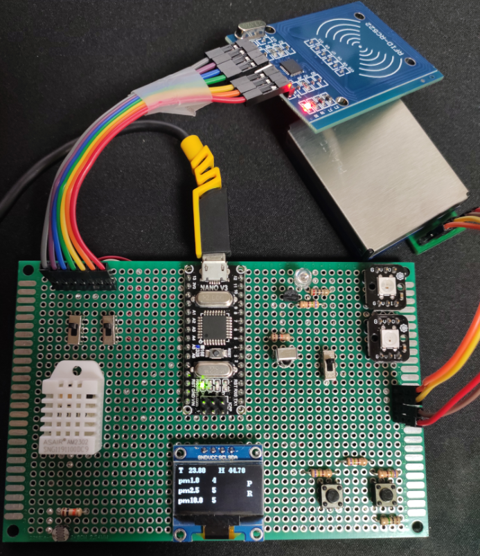
제작
핀 사용
| 아두이노 나노 | 핀 | 핀 | 부품 |
| A3 | A3 | 버튼 | |
| A4 | SCL | OLED 디스플레이 | |
| A5 | SDA | ||
| A6 | A6 | CDS | |
| D3 | IR LED | ||
| D4 | RX | PMS7003 | |
| D5 | IR receiver | ||
| D6 | I | 네오픽셀 LED | |
| D7 | TX | PMS7003 | |
| D9 | RST (7) |
RFID RC522 ()안에 숫자는 핀 순서 |
|
| D10 | SDA (1) | ||
| D11 | MOSI (3) | ||
| D12 | MISO (4) | ||
| D13 | SCK (2) |
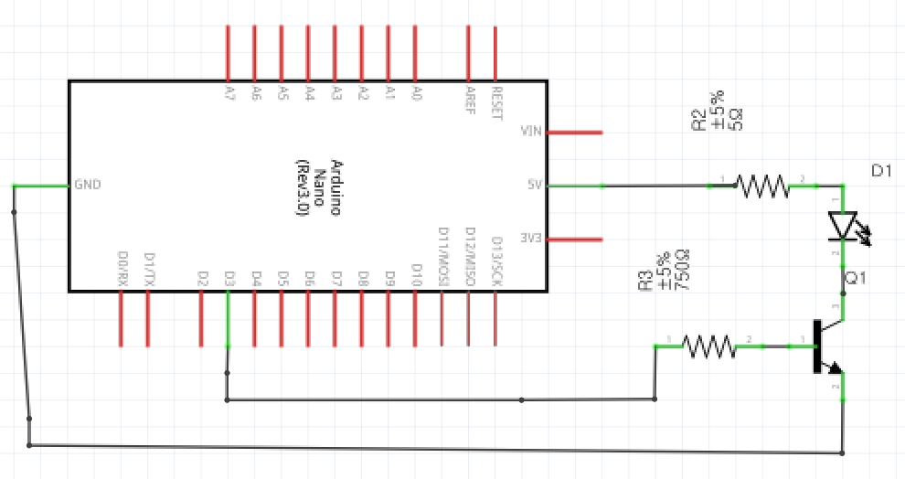
ir led는 발신 거리가 매우 짧다. 따라서 증폭회로를 구성하여 발신 거리를 늘려야만 한다.
ir led 증폭 회로 :
https://mandu-mandu.tistory.com/336
버튼을 두 개달 수 있는 두 개의 남는 디지털핀이 없다. 따라서 하나의 아날로그 핀을 이용해서 버튼 두 개를 모두 연결해주었다.
참고:
http://blog.naver.com/PostView.nhn?blogId=heungmusoft&logNo=220607169389
저는 여기서 750옴 3개와 1M옴 1개를 사용하였습니다. 750옴 3개 대신에 저항값이 같은 저항 3개를 사용하셔도 됩니다.(아마...)
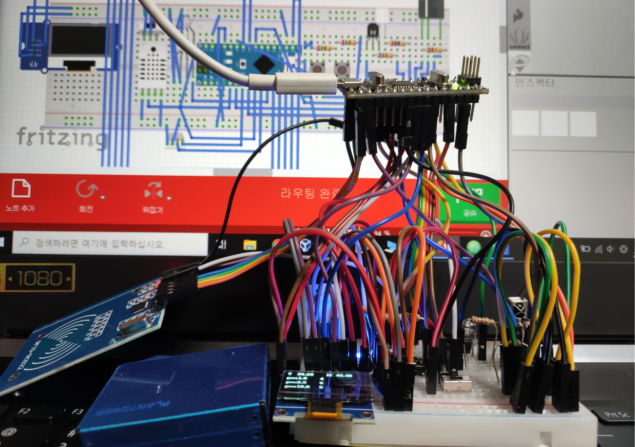
Fritzing 설계 및 제작
oled 디스플레이 핀 연결을 왼쪽에서는 SCL SDA 무시하고 위치에 맞게 연결. 오른쪽에서는 SCL SDA 맞춰서 연결.
실제 부품에서 SCL과 SDA의 순서가 달라서 그렇습니다.
왼쪽 배치도에서 D5와 연결된 트렌지스터는 트렌지스터가 아니라, IR 수신부입니다.
추가가 필요한 부품 파일:
DHT22
RFID RC522
네오픽셀 led랑 pms7003이 파일이 없어서 다른 부품으로 대체했다.

코드 작성
라이브러리에서 제공되는 예제 코드들을 활용했다.
센서랑 디스플레이는 아래 영상을 참고했다.
https://www.youtube.com/watch?v=yMIlVDL0C9s&t=224s
https://www.youtube.com/watch?v=qH650QLNrW4
메모리사용을 최대한 줄이기 위해서 시리얼 출력을 최대한 삭제하였다.
rfid 데이터 복제 기능을 따로 뺐기 때문에 코드는 2개로 나뉜다.
+ 두 개의 코드를 합친 코드도 같이 올렸다.
https://github.com/M4ndU/arduino
M4ndU/arduino
Hack tool made with Arduino. Contribute to M4ndU/arduino development by creating an account on GitHub.
github.com
project.ino
|
1
2
3
4
5
6
7
8
9
10
11
12
13
14
15
16
17
18
19
20
21
22
23
24
25
26
27
28
29
30
31
32
33
34
35
36
37
38
39
40
41
42
43
44
45
46
47
48
49
50
51
52
53
54
55
56
57
58
59
60
61
62
63
64
65
66
67
68
69
70
71
72
73
74
75
76
77
78
79
80
81
82
83
84
85
86
87
88
89
90
91
92
93
94
95
96
97
98
99
100
101
102
103
104
105
106
107
108
109
110
111
112
113
114
115
116
117
118
119
120
121
122
123
124
125
126
127
128
129
130
131
132
133
134
135
136
137
138
139
140
141
142
143
144
145
146
147
148
149
150
151
152
153
154
155
156
157
158
159
160
161
162
163
164
165
166
167
168
169
170
171
172
173
174
175
176
177
178
179
180
181
182
183
184
185
186
187
188
189
190
191
192
193
194
195
196
197
198
199
200
201
202
203
204
205
206
207
208
209
210
211
212
213
214
215
216
217
218
219
220
221
222
223
224
225
226
227
228
229
230
231
232
233
234
235
236
237
238
239
240
241
242
243
244
245
246
247
248
249
250
251
252
253
254
|
//스케치는 프로그램 저장 공간 28950 바이트(94%)를 사용. 최대 30720 바이트.
//전역 변수는 동적 메모리 1414바이트(69%)를 사용, 634바이트의 지역변수가 남음. 최대는 2048 바이트.
#include <DHT.h>
#include <Adafruit_NeoPixel.h>
#include <U8g2lib.h>
#include <PMS.h>
#include <SoftwareSerial.h>
#include <IRremote.h>
#include <SPI.h>
#include <MFRC522.h>
#define NEO_PIN 6
#define DHT_PIN 2
#define IRrecvPin 5 // An IR detector/demodulator is connected to GPIO pin 5
#define cdsPin A6
#define buttonPin A3 // select the input pin for the potentiometer
#define RST_PIN 9 // Configurable, see typical pin layout above
#define SS_PIN 10 // Configurable, see typical pin layout above
SoftwareSerial pmsSerial(7, 4); //RX, TX
PMS pms(pmsSerial);
PMS::DATA data;
byte pm25_status = 0;
byte pm100_status = 0;
U8G2_SSD1306_128X64_NONAME_1_HW_I2C u8g2(U8G2_R0);
Adafruit_NeoPixel neoPixel = Adafruit_NeoPixel(2, NEO_PIN, NEO_GRB + NEO_KHZ800);
const int neo_color[][3] = {{32, 32,32}, {0, 0, 32}, {0, 32, 0}, {32, 21, 0}, {32, 0, 0}, {16, 0, 0}, {0, 8, 0}};
byte neo_color_index=0;
DHT dht(DHT_PIN, DHT22);
float temp;
float humi;
char IRDisplayStr;
char RFIDDisplayStr;
MFRC522 mfrc522(SS_PIN, RST_PIN); // Create MFRC522 instance.
MFRC522::MIFARE_Key key;
byte newUid[10] = {0xDE, 0xAD, 0xBE, 0xEF};
bool IsRfidWriteMode = false;
// ==================== start of IRrecv config ====================
IRrecv irrecv(IRrecvPin);
decode_results results;
byte size_of_rawdata;
uint16_t *raw_data;
// ==================== end of of IRrecv config ====================
// ==================== start of IRsend config ====================
IRsend irsend; // An IR LED must be connected to Arduino PWM pin 3.
bool IRLED_SEND_SWITCH = false;
bool CLEAR_TO_SEND = false;
// ==================== end of of IRsend config ====================
//==================== start setup ====================
// This section of code runs only once at start-up.
void setup() {
pinMode(cdsPin, INPUT);
pinMode(buttonPin, INPUT);
Serial.begin(9600);
pmsSerial.begin(9600);
dht.begin();
u8g2.begin();
u8g2.enableUTF8Print();
neoPixel.begin();
neoPixel.show();
irrecv.enableIRIn();
SPI.begin(); // Init SPI bus
mfrc522.PCD_Init(); // Init MFRC522 card
}
//==================== end setup ====================
//==================== start rfid func ====================
void rfid_rw(bool w_mode) {
// Look for new cards
if ( ! mfrc522.PICC_IsNewCardPresent() || ! mfrc522.PICC_ReadCardSerial() ) {
return;
}
if(!w_mode)
{
//dump_uid
for (byte i = 0; i < mfrc522.uid.size; i++) {
newUid[i] = mfrc522.uid.uidByte[i];
}
// Dump debug info about the card; PICC_HaltA() is automatically called
mfrc522.PICC_DumpToSerial(&(mfrc522.uid));
}
else
{
// Set new UID
if ( mfrc522.MIFARE_SetUid(newUid, (byte)4, true) ) {
Serial.println(F("Wrote new UID to card."));
}
mfrc522.PICC_HaltA(); // Halt PICC
}
}
//==================== end rifd func ====================
//==================== start loop func ====================
void loop() {
if (irrecv.decode(&results)) {
irrecv.resume(); // Prepare for the next value
// resultToRawArray() allocates the memory we need for the array.
raw_data = results.rawbuf;
// Find out how many elements are in the array.
size_of_rawdata = results.rawlen;
CLEAR_TO_SEND = true;
}
if (IRLED_SEND_SWITCH){
if (CLEAR_TO_SEND){
irsend.sendRaw(raw_data, size_of_rawdata, 38); // Send a raw data capture at 38kHz.
delay(1000);
}
else {
IRLED_SEND_SWITCH = false;
}
}
int light = analogRead(cdsPin);
int buttonValue = analogRead(buttonPin);
if(buttonValue == 339) {
IRLED_SEND_SWITCH = !IRLED_SEND_SWITCH;
}
if(buttonValue == 682) {
IsRfidWriteMode = !IsRfidWriteMode;
}
if(buttonValue == 510) {
rfid_rw(IsRfidWriteMode);
}
if (IRLED_SEND_SWITCH){
IRDisplayStr = 'S'; //send mode
neo_color_index = 5;
} else{
IRDisplayStr = 'P';
neo_color_index = 0; //normal
}
if(IsRfidWriteMode){
RFIDDisplayStr = 'W'; //write
neo_color_index = 6;
} else {
RFIDDisplayStr = 'R'; //read
}
neoPixel.setPixelColor(1, neoPixel.Color(neo_color[neo_color_index][0],neo_color[neo_color_index][1],neo_color[neo_color_index][2]));
u8g2.setFont(u8g2_font_ncenB08_tr);
u8g2.setFontPosTop();
u8g2.setFontDirection(0);
u8g2.firstPage();
do{
temp = dht.readTemperature();
humi = dht.readHumidity();
if (pms.read(data)) {
if ((int) data.PM_AE_UG_2_5 < 9) {
pm25_status = 1;
}
else if (8 < (int) data.PM_AE_UG_2_5 && (int) data.PM_AE_UG_2_5 < 26) {
pm25_status = 2;
}
else if (25 < (int) data.PM_AE_UG_2_5 && (int) data.PM_AE_UG_2_5 < 76) {
pm25_status = 3;
}
else if (75 < (int) data.PM_AE_UG_2_5) {
pm25_status = 4;
}
if ((int) data.PM_AE_UG_10_0 < 16) {
pm100_status = 1;
}
else if (15 < (int) data.PM_AE_UG_10_0 && (int) data.PM_AE_UG_10_0 < 51) {
pm100_status = 2;
}
else if (50 < (int) data.PM_AE_UG_10_0 && (int) data.PM_AE_UG_10_0 < 150) {
pm100_status = 3;
}
else if (149 < (int) data.PM_AE_UG_10_0) {
pm100_status = 4;
}
}
neoPixel.setBrightness(light); //light값을 잘 다뤄보세요...
byte neo_status = max(pm25_status, pm100_status);
neoPixel.setPixelColor(0, neoPixel.Color(neo_color[neo_status][0],neo_color[neo_status][1],neo_color[neo_status][2]));
neoPixel.show();
u8g2.setCursor(0, 0);
u8g2.print(F("T"));
u8g2.setCursor(16, 0);
u8g2.print(temp);
u8g2.setCursor(64, 0);
u8g2.print(F("H"));
u8g2.setCursor(80, 0);
u8g2.print(humi);
u8g2.setCursor(0, 15);
u8g2.print(F("pm1.0"));
u8g2.setCursor(0, 30);
u8g2.print(F("pm2.5"));
u8g2.setCursor(0, 45);
u8g2.print(F("pm10.0"));
u8g2.setCursor(54, 15);
u8g2.print(data.PM_AE_UG_1_0);
u8g2.setCursor(54, 30);
u8g2.print(data.PM_AE_UG_2_5);
u8g2.setCursor(54, 45);
u8g2.print(data.PM_AE_UG_10_0);
u8g2.setCursor(110, 20);
u8g2.print((String)IRDisplayStr);
u8g2.setCursor(110, 35);
u8g2.print((String)RFIDDisplayStr);
}while(u8g2.nextPage());
}
//==================== end loop func ====================
|
cs |
only_rfid_data_copy.ino
|
1
2
3
4
5
6
7
8
9
10
11
12
13
14
15
16
17
18
19
20
21
22
23
24
25
26
27
28
29
30
31
32
33
34
35
36
37
38
39
40
41
42
43
44
45
46
47
48
49
50
51
52
53
54
55
56
57
58
59
60
61
62
63
64
65
66
67
68
69
70
71
72
73
74
75
76
77
78
79
80
81
82
83
84
85
86
87
88
89
90
91
92
93
94
95
96
97
98
99
100
101
102
103
104
105
106
107
108
109
110
111
112
113
114
115
116
117
118
119
120
121
122
123
124
125
126
127
128
129
130
131
132
133
134
135
136
137
138
139
140
141
142
143
144
145
146
147
148
149
150
151
152
153
154
155
156
157
158
159
160
161
162
163
164
165
166
167
168
169
170
171
172
173
174
175
176
177
178
179
180
181
182
183
184
185
186
187
188
189
190
191
192
193
194
195
196
197
198
199
200
201
202
203
204
205
206
207
208
209
210
211
212
213
214
215
216
217
218
219
220
221
222
223
224
225
226
227
228
229
230
231
232
233
234
235
236
237
238
239
240
241
242
243
244
245
246
247
248
249
250
251
252
253
254
255
256
257
258
259
260
261
262
263
264
265
266
267
268
269
270
271
272
273
274
275
276
|
//스케치는 프로그램 저장 공간 9272 바이트(30%)를 사용. 최대 30720 바이트.
//전역 변수는 동적 메모리 1436바이트(70%)를 사용, 612바이트의 지역변수가 남음. 최대는 2048 바이트.
#include <Adafruit_NeoPixel.h>
#include <SPI.h>
#include <MFRC522.h>
#define NEO_PIN 6
#define cdsPin A6
#define buttonPin A3 // select the input pin for the potentiometer
#define RST_PIN 9 // Configurable, see typical pin layout above
#define SS_PIN 10 // Configurable, see typical pin layout above
#define MENU_STR "button 1.R/W 2.mode"
Adafruit_NeoPixel neoPixel = Adafruit_NeoPixel(2, NEO_PIN, NEO_GRB + NEO_KHZ800);
const PROGMEM int8_t neo_color[][3] = {{32, 32,32}, {0, 0, 32}, {0, 32, 0}, {32, 21, 0}, {32, 0, 0}, {16, 0, 0}, {0, 8, 0}};
int8_t neo_color_index=0;
MFRC522 mfrc522(SS_PIN, RST_PIN); // Create MFRC522 instance.
byte buffer[18];
byte block;
byte waarde[64][16];
MFRC522::StatusCode status;
MFRC522::MIFARE_Key key;
// Number of known default keys (hard-coded)
// NOTE: Synchronize the NR_KNOWN_KEYS define with the defaultKeys[] array
#define NR_KNOWN_KEYS 8
// Known keys, see: https://code.google.com/p/mfcuk/wiki/MifareClassicDefaultKeys
byte knownKeys[NR_KNOWN_KEYS][MFRC522::MF_KEY_SIZE] = {
{0xff, 0xff, 0xff, 0xff, 0xff, 0xff}, // FF FF FF FF FF FF = factory default
{0xa0, 0xa1, 0xa2, 0xa3, 0xa4, 0xa5}, // A0 A1 A2 A3 A4 A5
{0xb0, 0xb1, 0xb2, 0xb3, 0xb4, 0xb5}, // B0 B1 B2 B3 B4 B5
{0x4d, 0x3a, 0x99, 0xc3, 0x51, 0xdd}, // 4D 3A 99 C3 51 DD
{0x1a, 0x98, 0x2c, 0x7e, 0x45, 0x9a}, // 1A 98 2C 7E 45 9A
{0xd3, 0xf7, 0xd3, 0xf7, 0xd3, 0xf7}, // D3 F7 D3 F7 D3 F7
{0xaa, 0xbb, 0xcc, 0xdd, 0xee, 0xff}, // AA BB CC DD EE FF
{0x00, 0x00, 0x00, 0x00, 0x00, 0x00} // 00 00 00 00 00 00
};
byte newUid[10] = {0xDE, 0xAD, 0xBE, 0xEF};
bool IsRfidWriteMode = false;
//==================== start setup ====================
// This section of code runs only once at start-up.
void setup() {
pinMode(cdsPin, INPUT);
pinMode(buttonPin, INPUT);
Serial.begin(9600);
while (!Serial); // Do nothing if no serial port is opened (added for Arduinos based on ATMEGA32U4)
SPI.begin(); // Init SPI bus
mfrc522.PCD_Init(); // Init MFRC522 card
Serial.println(MENU_STR);
neoPixel.begin();
neoPixel.show();
}
//==================== end setup ====================
//==================== start rfid func ====================
//Via seriele monitor de bytes uitlezen in hexadecimaal
void dump_byte_array(byte *buffer, byte bufferSize) {
for (byte i = 0; i < bufferSize; i++) {
Serial.print(buffer[i] < 0x10 ? " 0" : " ");
Serial.print(buffer[i], HEX);
}
}
//Via seriele monitor de bytes uitlezen in ASCI
void dump_byte_array1(byte *buffer, byte bufferSize) {
for (byte i = 0; i < bufferSize; i++) {
Serial.print(buffer[i] < 0x10 ? " 0" : " ");
Serial.write(buffer[i]);
}
}
/*
* Try using the PICC (the tag/card) with the given key to access block 0 to 63.
* On success, it will show the key details, and dump the block data on Serial.
*
* @return true when the given key worked, false otherwise.
*/
bool check_status_failed(MFRC522::StatusCode ck_status){
if (ck_status != MFRC522::STATUS_OK) {
Serial.print(F("failed: "));
Serial.println(mfrc522.GetStatusCodeName(status));
return true;
}
return false;
}
void end_rc522_sign(){
mfrc522.PICC_HaltA(); // Halt PICC
mfrc522.PCD_StopCrypto1(); // Stop encryption on PCD
}
bool try_key(MFRC522::MIFARE_Key *key)
{
bool result = false;
for(byte block = 0; block < 64; block++){
// Serial.println(F("Authenticating using key A..."));
status = mfrc522.PCD_Authenticate(MFRC522::PICC_CMD_MF_AUTH_KEY_A, block, key, &(mfrc522.uid));
if (check_status_failed(status)) {
return false;
}
// Read block
byte byteCount = sizeof(buffer);
status = mfrc522.MIFARE_Read(block, buffer, &byteCount);
if (!check_status_failed(status)) {
// Successful read
result = true;
Serial.print(F("Succ key:"));
dump_byte_array((*key).keyByte, MFRC522::MF_KEY_SIZE);
Serial.println();
//dump_uid
for (int i = 0; i < mfrc522.uid.size; i++) {
newUid[i] = mfrc522.uid.uidByte[i];
}
// Dump block data
Serial.print(F("Block ")); Serial.print(block); Serial.print(F(":"));
dump_byte_array1(buffer, 16); //omzetten van hex naar ASCI
Serial.println();
for (int p = 0; p < 16; p++) //De 16 bits uit de block uitlezen
{
waarde [block][p] = buffer[p];
Serial.print(waarde[block][p]);
Serial.print(" ");
}
}
}
Serial.println();
Serial.println(MENU_STR);
end_rc522_sign();
return result;
}
void rfid_rw(bool writemode) {
Serial.println(F("Insert card..."));
// Look for new cards
if ( ! mfrc522.PICC_IsNewCardPresent() || ! mfrc522.PICC_ReadCardSerial() ) {
return;
}
// Show some details of the PICC (that is: the tag/card)
Serial.print(F("Card UID:"));
dump_byte_array(mfrc522.uid.uidByte, mfrc522.uid.size);
Serial.println();
Serial.print(F("PICC type: "));
MFRC522::PICC_Type piccType = mfrc522.PICC_GetType(mfrc522.uid.sak);
Serial.println(mfrc522.PICC_GetTypeName(piccType));
if(!writemode)
{
Serial.println(F("Read"));
// Try the known default keys
MFRC522::MIFARE_Key key;
for (byte k = 0; k < NR_KNOWN_KEYS; k++) {
// Copy the known key into the MIFARE_Key structure
for (byte i = 0; i < MFRC522::MF_KEY_SIZE; i++) {
key.keyByte[i] = knownKeys[k][i];
}
// Try the key
if (try_key(&key)) {
// Found and reported on the key and block,
// no need to try other keys for this PICC
break;
}
}
}
else
{
Serial.println(F("Copy to the new card"));
for (byte i = 0; i < 6; i++) {
key.keyByte[i] = 0xFF;
}
for(int i = 4; i <= 62; i++){ //De blocken 4 tot 62 kopieren, behalve al deze onderstaande blocken (omdat deze de authenticatie blokken zijn)
if(i == 7 || i == 11 || i == 15 || i == 19 || i == 23 || i == 27 || i == 31 || i == 35 || i == 39 || i == 43 || i == 47 || i == 51 || i == 55 || i == 59){
i++;
}
block = i;
// Authenticate using key A
Serial.println(F("Authenticating using key A..."));
status = (MFRC522::StatusCode) mfrc522.PCD_Authenticate(MFRC522::PICC_CMD_MF_AUTH_KEY_A, block, &key, &(mfrc522.uid));
if (check_status_failed(status)) {
return;
}
// Authenticate using key B
Serial.println(F("Authenticating again using key B..."));
status = (MFRC522::StatusCode) mfrc522.PCD_Authenticate(MFRC522::PICC_CMD_MF_AUTH_KEY_B, block, &key, &(mfrc522.uid));
if (check_status_failed(status)) {
return;
}
/*
// Set new UID
if ( mfrc522.MIFARE_SetUid(newUid, (byte)4, true) ) {
Serial.println(F("Wrote new UID to card."));
}
*/
// Write data to the block
Serial.print(F("Writing data into block "));
Serial.print(block);
Serial.println("\n");
dump_byte_array(waarde[block], 16);
status = (MFRC522::StatusCode) mfrc522.MIFARE_Write(block, waarde[block], 16);
check_status_failed(status);
Serial.println("\n");
}
end_rc522_sign();
Serial.println(MENU_STR);
}
}
//==================== end rfid func ====================
//==================== start loop func ====================
void loop() {
int8_t light = analogRead(cdsPin);
int8_t brightness = map(light/2, 0, 1024, 255, 0);
int16_t buttonValue = analogRead(buttonPin);
if(buttonValue == 339) {
rfid_rw(IsRfidWriteMode);
}
if(buttonValue == 682) {
IsRfidWriteMode = !IsRfidWriteMode;
}
if (IsRfidWriteMode){
neo_color_index = 5;
} else{
neo_color_index = 0; //READ MODE
}
neoPixel.setPixelColor(1, neoPixel.Color(neo_color[neo_color_index][0],neo_color[neo_color_index][1],neo_color[neo_color_index][2]));
neoPixel.setBrightness(brightness);
neoPixel.show();
}
//==================== end loop func ====================
|
cs |
all.ino
|
1
2
3
4
5
6
7
8
9
10
11
12
13
14
15
16
17
18
19
20
21
22
23
24
25
26
27
28
29
30
31
32
33
34
35
36
37
38
39
40
41
42
43
44
45
46
47
48
49
50
51
52
53
54
55
56
57
58
59
60
61
62
63
64
65
66
67
68
69
70
71
72
73
74
75
76
77
78
79
80
81
82
83
84
85
86
87
88
89
90
91
92
93
94
95
96
97
98
99
100
101
102
103
104
105
106
107
108
109
110
111
112
113
114
115
116
117
118
119
120
121
122
123
124
125
126
127
128
129
130
131
132
133
134
135
136
137
138
139
140
141
142
143
144
145
146
147
148
149
150
151
152
153
154
155
156
157
158
159
160
161
162
163
164
165
166
167
168
169
170
171
172
173
174
175
176
177
178
179
180
181
182
183
184
185
186
187
188
189
190
191
192
193
194
195
196
197
198
199
200
201
202
203
204
205
206
207
208
209
210
211
212
213
214
215
216
217
218
219
220
221
222
223
224
225
226
227
228
229
230
231
232
233
234
235
236
237
238
239
240
241
242
243
244
245
246
247
248
249
250
251
252
253
254
255
256
257
258
259
260
261
262
263
264
265
266
267
268
269
270
271
272
273
274
275
276
277
278
279
280
281
282
283
284
285
286
287
288
289
290
291
292
293
294
295
296
297
298
299
300
301
302
303
304
305
306
307
308
309
310
311
312
313
314
315
316
317
318
319
320
321
322
323
324
325
326
327
328
329
330
331
332
333
334
335
336
337
338
339
340
341
342
343
344
345
346
347
348
349
350
351
352
353
354
355
356
357
358
359
360
361
|
//스케치는 프로그램 저장 공간 25636 바이트(83%)를 사용. 최대 30720 바이트.
//전역 변수는 동적 메모리 2410바이트(117%)를 사용, -362바이트의 지역변수가 남음. 최대는 2048 바이트.
#include <DHT.h>
#include <Adafruit_NeoPixel.h>
#include <U8g2lib.h>
#include <PMS.h>
#include <SoftwareSerial.h>
#include <IRremote.h>
#include <SPI.h>
#include <MFRC522.h>
#define NEO_PIN 6
#define DHT_PIN 2
#define IRrecvPin 5 // An IR detector/demodulator is connected to GPIO pin 5
#define cdsPin A6
#define buttonPin A3 // select the input pin for the potentiometer
#define RST_PIN 9 // Configurable, see typical pin layout above
#define SS_PIN 10 // Configurable, see typical pin layout above
SoftwareSerial pmsSerial(7, 4); //RX, TX
PMS pms(pmsSerial);
PMS::DATA data;
byte pm25_status = 0;
byte pm100_status = 0;
U8G2_SSD1306_128X64_NONAME_1_HW_I2C u8g2(U8G2_R0);
Adafruit_NeoPixel neoPixel = Adafruit_NeoPixel(2, NEO_PIN, NEO_GRB + NEO_KHZ800);
const int neo_color[][3] = {{32, 32,32}, {0, 0, 32}, {0, 32, 0}, {32, 21, 0}, {32, 0, 0}, {16, 0, 0}, {0, 8, 0}};
byte neo_color_index=0;
DHT dht(DHT_PIN, DHT22);
float temp;
float humi;
char IRDisplayStr;
char RFIDDisplayStr;
MFRC522 mfrc522(SS_PIN, RST_PIN); // Create MFRC522 instance.
byte buffer[18];
byte block;
byte waarde[64][16];
MFRC522::StatusCode status;
MFRC522::MIFARE_Key key;
// Number of known default keys (hard-coded)
// NOTE: Synchronize the NR_KNOWN_KEYS define with the defaultKeys[] array
#define NR_KNOWN_KEYS 8
// Known keys, see: https://code.google.com/p/mfcuk/wiki/MifareClassicDefaultKeys
byte knownKeys[NR_KNOWN_KEYS][MFRC522::MF_KEY_SIZE] = {
{0xff, 0xff, 0xff, 0xff, 0xff, 0xff}, // FF FF FF FF FF FF = factory default
{0xa0, 0xa1, 0xa2, 0xa3, 0xa4, 0xa5}, // A0 A1 A2 A3 A4 A5
{0xb0, 0xb1, 0xb2, 0xb3, 0xb4, 0xb5}, // B0 B1 B2 B3 B4 B5
{0x4d, 0x3a, 0x99, 0xc3, 0x51, 0xdd}, // 4D 3A 99 C3 51 DD
{0x1a, 0x98, 0x2c, 0x7e, 0x45, 0x9a}, // 1A 98 2C 7E 45 9A
{0xd3, 0xf7, 0xd3, 0xf7, 0xd3, 0xf7}, // D3 F7 D3 F7 D3 F7
{0xaa, 0xbb, 0xcc, 0xdd, 0xee, 0xff}, // AA BB CC DD EE FF
{0x00, 0x00, 0x00, 0x00, 0x00, 0x00} // 00 00 00 00 00 00
};
byte newUid[10] = {0xDE, 0xAD, 0xBE, 0xEF};
bool IsRfidWriteMode = false;
// ==================== start of IRrecv config ====================
IRrecv irrecv(IRrecvPin);
decode_results results;
byte size_of_rawdata;
uint16_t *raw_data;
// ==================== end of of IRrecv config ====================
// ==================== start of IRsend config ====================
IRsend irsend; // An IR LED must be connected to Arduino PWM pin 3.
bool IRLED_SEND_SWITCH = false;
bool CLEAR_TO_SEND = false;
// ==================== end of of IRsend config ====================
//==================== start setup ====================
// This section of code runs only once at start-up.
void setup() {
pinMode(cdsPin, INPUT);
pinMode(buttonPin, INPUT);
Serial.begin(9600);
pmsSerial.begin(9600);
dht.begin();
u8g2.begin();
u8g2.enableUTF8Print();
neoPixel.begin();
neoPixel.show();
irrecv.enableIRIn();
SPI.begin(); // Init SPI bus
mfrc522.PCD_Init(); // Init MFRC522 card
}
//==================== end setup ====================
//==================== start rfid func ====================
bool check_status_failed(MFRC522::StatusCode ck_status){
if (ck_status != MFRC522::STATUS_OK) {
Serial.print(F("failed: "));
Serial.println(mfrc522.GetStatusCodeName(status));
return true;
}
return false;
}
void rc522_epil(){
mfrc522.PICC_HaltA(); // Halt PICC
mfrc522.PCD_StopCrypto1(); // Stop encryption on PCD
}
bool try_key(MFRC522::MIFARE_Key *key)
{
bool result = false;
for(byte block = 0; block < 64; block++){
// Serial.println(F("Authenticating using key A..."));
status = mfrc522.PCD_Authenticate(MFRC522::PICC_CMD_MF_AUTH_KEY_A, block, key, &(mfrc522.uid));
if (check_status_failed(status)) {
return false;
}
// Read block
byte byteCount = sizeof(buffer);
status = mfrc522.MIFARE_Read(block, buffer, &byteCount);
if (!check_status_failed(status)) {
// Successful read
result = true;
//dump_uid
for (byte i = 0; i < mfrc522.uid.size; i++) {
newUid[i] = mfrc522.uid.uidByte[i];
}
// Dump block data
for (byte p = 0; p < 16; p++)
{
waarde [block][p] = buffer[p];
}
}
}
rc522_epil();
return result;
}
void rfid_rw(bool w_mode) {
// Look for new cards
if ( ! mfrc522.PICC_IsNewCardPresent() || ! mfrc522.PICC_ReadCardSerial() ) {
return;
}
if(!w_mode)
{
// Try the known default keys
MFRC522::MIFARE_Key key;
for (byte k = 0; k < NR_KNOWN_KEYS; k++) {
// Copy the known key into the MIFARE_Key structure
for (byte i = 0; i < MFRC522::MF_KEY_SIZE; i++) {
key.keyByte[i] = knownKeys[k][i];
}
// Try the key
if (try_key(&key)) {
// Found and reported on the key and block,
// no need to try other keys for this PICC
break;
}
}
}
else
{
for (byte i = 0; i < 6; i++) {
key.keyByte[i] = 0xFF;
}
for(byte i = 4; i <= 62; i++){
if(i == 7 || i == 11 || i == 15 || i == 19 || i == 23 || i == 27 || i == 31 || i == 35 || i == 39 || i == 43 || i == 47 || i == 51 || i == 55 || i == 59){
i++;
}
block = i;
// Authenticate using key A
status = (MFRC522::StatusCode) mfrc522.PCD_Authenticate(MFRC522::PICC_CMD_MF_AUTH_KEY_A, block, &key, &(mfrc522.uid));
if (check_status_failed(status)) {
return;
}
// Authenticate using key B
status = (MFRC522::StatusCode) mfrc522.PCD_Authenticate(MFRC522::PICC_CMD_MF_AUTH_KEY_B, block, &key, &(mfrc522.uid));
if (check_status_failed(status)) {
return;
}
/*
// Set new UID
if ( mfrc522.MIFARE_SetUid(newUid, (byte)4, true) ) {
Serial.println(F("Wrote new UID to card."));
}
*/
// Write data to the block
status = (MFRC522::StatusCode) mfrc522.MIFARE_Write(block, waarde[block], 16);
check_status_failed(status);
}
rc522_epil();
}
}
//==================== end rifd func ====================
//==================== start loop func ====================
void loop() {
if (irrecv.decode(&results)) {
irrecv.resume(); // Prepare for the next value
// resultToRawArray() allocates the memory we need for the array.
raw_data = results.rawbuf;
// Find out how many elements are in the array.
size_of_rawdata = results.rawlen;
CLEAR_TO_SEND = true;
}
if (IRLED_SEND_SWITCH){
if (CLEAR_TO_SEND){
irsend.sendRaw(raw_data, size_of_rawdata, 38); // Send a raw data capture at 38kHz.
delay(1000);
}
else {
IRLED_SEND_SWITCH = false;
}
}
int16_t light = analogRead(cdsPin);
int16_t brightness = map(light / 2, 0, 1024, 255, 0);
int16_t buttonValue = analogRead(buttonPin);
if(buttonValue == 339) {
IRLED_SEND_SWITCH = !IRLED_SEND_SWITCH;
}
if(buttonValue == 682) {
IsRfidWriteMode = !IsRfidWriteMode;
}
if(buttonValue == 900) {
rfid_rw(IsRfidWriteMode);
}
if (IRLED_SEND_SWITCH){
IRDisplayStr = 'S';
neo_color_index = 5;
} else{
IRDisplayStr = 'P';
neo_color_index = 0; //normal
}
if(IsRfidWriteMode){
RFIDDisplayStr = 'W';
neo_color_index = 6;
} else {
RFIDDisplayStr = 'R';
}
neoPixel.setPixelColor(1, neoPixel.Color(neo_color[neo_color_index][0],neo_color[neo_color_index][1],neo_color[neo_color_index][2]));
u8g2.setFont(u8g2_font_ncenB08_tr);
u8g2.setFontPosTop();
u8g2.setFontDirection(0);
u8g2.firstPage();
do{
temp = dht.readTemperature();
humi = dht.readHumidity();
if (pms.read(data)) {
if ((int) data.PM_AE_UG_2_5 < 9) {
pm25_status = 1;
}
else if (8 < (int) data.PM_AE_UG_2_5 && (int) data.PM_AE_UG_2_5 < 26) {
pm25_status = 2;
}
else if (25 < (int) data.PM_AE_UG_2_5 && (int) data.PM_AE_UG_2_5 < 76) {
pm25_status = 3;
}
else if (75 < (int) data.PM_AE_UG_2_5) {
pm25_status = 4;
}
if ((int) data.PM_AE_UG_10_0 < 16) {
pm100_status = 1;
}
else if (15 < (int) data.PM_AE_UG_10_0 && (int) data.PM_AE_UG_10_0 < 51) {
pm100_status = 2;
}
else if (50 < (int) data.PM_AE_UG_10_0 && (int) data.PM_AE_UG_10_0 < 150) {
pm100_status = 3;
}
else if (149 < (int) data.PM_AE_UG_10_0) {
pm100_status = 4;
}
}
neoPixel.setBrightness(brightness);
byte neo_status = max(pm25_status, pm100_status);
neoPixel.setPixelColor(0, neoPixel.Color(neo_color[neo_status][0],neo_color[neo_status][1],neo_color[neo_status][2]));
neoPixel.show();
u8g2.setCursor(0, 0);
u8g2.print(F("T"));
u8g2.setCursor(16, 0);
u8g2.print(temp);
u8g2.setCursor(64, 0);
u8g2.print(F("H"));
u8g2.setCursor(80, 0);
u8g2.print(humi);
u8g2.setCursor(0, 15);
u8g2.print(F("pm1.0"));
u8g2.setCursor(0, 30);
u8g2.print(F("pm2.5"));
u8g2.setCursor(0, 45);
u8g2.print(F("pm10.0"));
u8g2.setCursor(54, 15);
u8g2.print(data.PM_AE_UG_1_0);
u8g2.setCursor(54, 30);
u8g2.print(data.PM_AE_UG_2_5);
u8g2.setCursor(54, 45);
u8g2.print(data.PM_AE_UG_10_0);
u8g2.setCursor(110, 20);
u8g2.print((String)IRDisplayStr);
u8g2.setCursor(110, 35);
u8g2.print((String)RFIDDisplayStr);
}while(u8g2.nextPage());
}
//==================== end loop func ====================
|
cs |
'Project > Arduino' 카테고리의 다른 글
| 아두이노로 해킹도구 만들기 (1) - esp8266 deauther (0) | 2019.12.03 |
|---|---|
| IR led 신호 증폭 회로 (1) | 2019.12.02 |
| 아두이노로 해킹도구 만들기 (0) - 비하인드 스토리 (0) | 2019.12.02 |